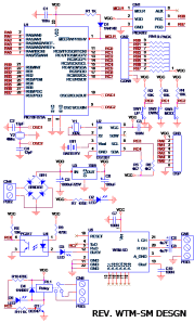
This project is a 25 memory audio annunciator with a battery backed up RTC Clock. The main function of this interface / Kit is to annunciate a voice message at a given programmed time stored in it. The main component of the system are , an LCD to display the present activity of the project / Kit, a battery backed up RTC (Real Time Clock), the function of which is to provide an accurate clock signal to the Microcontroller, a 3 Key configuration Setup and a MP3 Player module with a SD card as a storage medium for audio files.
The basic logic of operation is that its keeps comparing the Alarm Set timing with the RTC and when a match occurs, it plays / annunciate, a particular Audio file associated with the Alarm, stored on the SD card on the MP3 module.
Salient features –
- Supports upto 25 memory (Alarm) location and 9 audio files for playback with Loop Option.
- A battery backed up RTC (Real Time Clock)
- Polarity independent DC input. DC input upto 30V can be provided.
- Switch Mode Power Supply Design to handle more current required by the module and higher DC input.
- Power On LED indicator
- 16×2 Backlight, Alfa Numeric LCD for showing the current situation of the Kit and aiding to help in configuration and setting of the Alarms and RTC time.
- Relay operation (with LED Indication) during Alarm situation to drive or switch further circuit that may be required.
- A Busy LED indicator to display Audio being played during Alarm situation, both on PCB and MP3 Module.
- Industrial Class, PBT connectors for connection I/O wires to/fro board.
- MP3 module, plug in type with Box header. Storage format / Medium for audio is mp3 (8~320Kbps) on SD card.
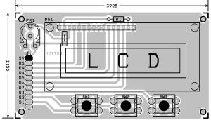
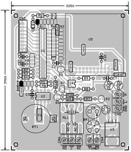
- Glass Epoxy PCB measuring , Main Board – 3.250 x 3.900 inch. LCD – 3.925 x 2.150
Application Areas:
- Time based Annunciation of important information in an Industrial environment.
- Time based Prayer chanter for religious establishment
- Time based Audio Reminder, for attention, for the elderly and dependent people.
Operation:
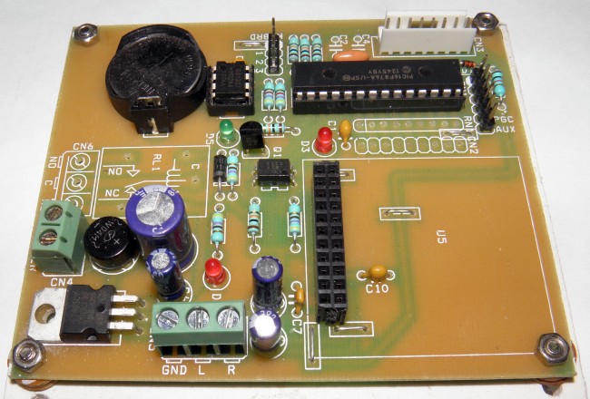
Power Supply to this board should be DC 8 ~ 12V @ 500 mA. Power is connected at Connector marked CN4. LED marked D2 indicates Power on board. Two bridged relimate connectors with wire pop out of the LCD+3 Keys PCB. The LCD connector (8 pin Relimate) connects at CN3 and the other 3 pin Connector (Keys) connects at connector marked “KYBRD” on the PCB.
Please ensure, that before you connect the power –
- MP3 Module with SD Card holding audio files is installed on the PCB.
- LCD module pack is installed on the PCB.
- RTC Battery is placed, in the PCB mounted Battery holder, for powering the RTC
- Audio output is properly routed to your Audio chain.
- Relay Output is properly connected.
Please remember
- D2 LED provides Power On indication for the PCB.
- D3 LED provides Busy indication for the MP3 Module. It duplicates the function of the LED onboard the MP3 module.
- CN5 provides Audio output of the Board. Please remember the Centre pin is Ground.
- CN6 provides Potential free contact of the Relay on board , which can be used to switch external device, during play of the audio file. LED D5 provides Relay on indicator.
- BT1 holds a CR2032 (3V) Button Cell, which Powers the RTC , when Power is off , to this board. The life expectancy of this battery would be more than 1 year, but might need a change if there’s a frequent loss of time over a period of time.
- The LCD connect to CN3 Connector on the PCB. And the Keys part connect to area marked KYBRD
- You will need an Audio Amplifier kit to drive the Speaker and any Stereo amplifier kit (TDA2833) would do.
When properly connected and powered on , the LCD should display this –
This indicates that the firmware is Rev. E and modified (written) on 14.03.2013. This screen rename active for 2 Sec and moves on to show the Timer Detail view.
This screen displays, on the top line, next alarm details. In this example seen on top its read as , next alarm is scheduled to be on 13:30, Audio file chosen for playback is No.15 and this is 5th. Alarm from a maximum of 10. The second line displays the Current time.
Setting the RTC :
Setting the RTC Date/Time is done by the 3 keys available on the LCD PCB. SW3 is Mode/Set select key, SW1 is increment and SW2 is decrement value. To set the onboard Clock Date/Time, you must first press the Mode/Set key once. Here the LCD will show you an option , if you want to set the RTC Date/Time or Alarms Setting.
Press SW1 (Increment) switch to enter RTC configuration or press SW2 to enter Alarm Setting. Now that you have chosen to set the RTC Date/Time, you will be prompted to set the RTC Hour.
Use the SW1/SW2 key to select the correct Hour and press the Mode/Set key. This will now prompt to set the RTC Mins.
Follow the same procedure you followed for the Hour setting and press the Mode/Set Switch. This will update the Hour and Mins of the Clock and come out. Seconds are reset to “00” value and updated. If all goes well you should see the new set time running. If at any given time you need to skip , setting of the Hour, you can press the Mode/Set key and it jumps to the next option.
Setting of Alarm :
To set the Alarm Parameter you need to press the Mode/Set switch once, this will prompt you with an option to set the Alarm or RTC . Select Alarm by pressing SW2 (Decrement) switch. The first option available to you is to set the Alarm Hour.
Press the UP/DOWN (SW1/SW2) key to select your desired Alarm hour and press SW3 (SET/MODE) switch. This will now take you to set the Mins parameter , follow the same procedure you followed for Hour setting.
The next parameter (Press Set/Mode SW) to set is the Message number. This indicates the audio file that you wish to play at this Alarm time, stored on the SD card.
Although this option shows you a Max. of 25 audio files , this version of the firmware is limited to just 10.
The next option (Press Set/Mode SW) that available , is the Relay OnTime delay. Which simply means for how long you want the Relay to be On. This time is in SECONDS.
The above example shows a delay of 3 seconds. Finally you need to write all this information on the chip’s non volatile memory. This screen appears when you press the next key (Press Set/Mode SW).
Pressing the Set/Mode key will write to memory and pressing any other key will ignore the changes and loop back to the next alarm. You could simple keep jumping to the next option by pressing Set/Mode switch on the LCD PCB. Keeping / Setting the Hours and Minutes to “00”, will skip this alarm and jump to the next valid stored alarm set. This way you can control the number of alarms you want to use in this hardware.
For any given reason you wish to advance (skip to next) set Alarm or Fall back to the previous Alarm , during normal operation, you can do this by pressing the Increment / Decrement Switch.


